Monday, August 5, 2013

Radio Control

One problem solved....


I recently bought an RC car in Hong Kong for $15 USA.
These cheap cars have remote controllers that to not have variable speeds, just

MOTOR +, MOTOR -, MOTOR RIGHT, MOTOR LEFT

This is absolutely perfect for my needs in this shot clock.
I have three controls: RESTART, PAUSE, RESET.

So, I took apart the vehicle  and pulled out the circuit board (left)
(Remote controller on the right)
Lets get some basics down on these circuits.
When the FORWARD button is pressed on the remote controller, it sends data over the 27MHz radio wave
The receiving board receives that data and turns on a motor to move FORWARD
Using this circuit, I can replace the FORWARD motor with a transistor
When the receiving board outputs a voltage signal to where the FORWARD motor once was, it will send a signal to the base of an NPN transistor

The transistor will connect the collector to the emitter.


How can i use this?
If you look at my prototype PCB, you will notice that I intended it to be handheld, or to be rested on a table.
Eventually, when this project is finished, I will need to place the PCB on the basketball backboard. The control buttons will be inaccessible to the bench.

So, when that time comes, I will connect the receiving board to the prototype PCB and replace the button switches with transistors.

This way, the bench can control the shot clock,

wirelessly

This is pretty cool to me. I hope it's cool to everyone else too.

This is the shot clock that will change the game.

Tuesday, July 23, 2013

Parts and PCB

Parts

Alrighty, anyone who likes to buy a lot of parts would know that Radioshack is a terrible place to go.
Compared the the prices you can find online, Radioshack is 500% or more overpriced
Plus, Radioshack is extremely limited in variety
But, what can I say. It's Radioshack. It sells cell phones.

So, being in HK I took the advantage of buying some parts in Sham Sui Po (heaven).
I went to this WECL store, bought $545 HKD worth of stuff. Well worth it: stocking up for the states!

Can you believe it? One heaping pack of resistors costed $5 HKD. Thats less than a US dollar.
Microphones, lasers, buttons, All less than one US dollar.
You can imagine how much I bought:

Sadly, and as I expected, I couldn't find flex resistors. They're hard to find: I guess I'll just have to order it.

PCB

https://drive.google.com/folderview?id=0B5gFDZ2efTDSX0hPdG5sWWJuemc&usp=sharing

That's the link to sharing all of the files. Updated.
There is a README there.

I highly recommend David Cook's Copper Connection software for hobbyists. It's free, easy to use, and tailored to the hobbyist needs.

Anyways, I'm in HK, away from my equipment, so I can't make the PCB yet.
this PCB is for testing out different sensors, so I guess it is a prototyping PCB.

The smaller PCB is for the phototransistor. It is separate.
I still need to work on deciding if I want to use flex resistors or piezo elements...


Cheers!


This is the shot clock that will change the game.

Monday, July 22, 2013

Still working!

Hello!
This is TS Wang, writing from Hong Kong.

Today we go parts shopping: many parts for the price of few parts (in the US)

While I wait on that, I have been working on my prototype PCB design on the plane and on each morning.


Once I'm finished I shall update the Google Drive folder with my recent documentation.

Oh by the way, just to get the word out, I'm using David Cook's Copper Connection.
It can be downloaded here: http://www.robotroom.com/CopperConnection/

It's great software, perfect for people who make PCBs at home. I used to use ExpressPCB, but now I use this. It's excellent.

Anyways, If anyone wants to email me at twang@ctemc.org to tell me how horrible my PCB design is, go ahead!

When the day ends today, I should have all the parts that I need for this project.

This is the shot clock that will change the game.

Monday, July 15, 2013

Decision time...

While I am in Hong Kong, I should be searching for some unique parts that might help out this project.
The predicament I'm working on currently, are the sensors.

The flex resistor:

courtesy of Sparkfun


I can use this as a voltage divider, so when flexed, will generate a voltage between 0v - 5v.
However, these are pretty expensive, and I'm not sure how sensitive they are to surface vibration (not flexing, as they will be smacked onto the back of a backboard, and on the rim.)


The piezo sensor:

courtesy of Sparkfun


These are cheap, these are commonly used, and these would be the first thing to come to mind when the two words "vibration sensor" popped-up.
There's a problem, however. They generate high voltages, for a very brief amount of time. These voltages are analog and above 5v, so my Attiny won't be able to read the whole range of voltage.
This is a good sensor to use when simply sensing vibrations, but not when it is needed to measure and compare vibrations.

I connected this sensor in parallel with a capacitor, (103, 104, I tried both, whatever was available) and it did well in lowering the analog signals that came through.

Serial.println(analogRead(A0));
like so.
The printed values ranged from 0 - 30. the maximum value Arduino can print is 1023.

I noticed, however (with and without the capacitor) that when the sensor was at a low state, the numbers kept creeping up, for example

1023
300
301
300
305
900
1023
1023
1023
350


Do you notice how the numbers just keep rising when it is at the low state (300 - 400)?
This isn't too good, as I will be comparing the voltages of two sensors. If this happens:

Backboard sensor: 301
Rim sensor: 304

the shot clock would reset. Not good.


Something else:

Maybe some expensive accelerometer might solve the problem, or something that will sense EXACTLY where the ball hit, just like humans can.


********************************************************************************
other than that, I am currently researching where to place the backboard sensor on the whole wide backboard. Does it matter; is there a significant difference to where I place it?

I'm finding out.


This is the shot clock that will change the game.


Thursday, July 11, 2013

Hong Kong Shopping - Parts

I have been in Canada for a week.

Next week, I shall be in Hong Kong, which is a great opportunity to search for cheap and hard to find parts.

I can definitely find the some sort of flex sensor, the laser, and anything else I might need.

I will keep you updated!

This is the shot clock that will change the game.

Saturday, June 29, 2013

So I just realized I can add post titles

Wow, I didn't know that.

Anyways, today I went on searching for flex resistors. I can usually find a really nice deal on ebay, but this time I'm out of luck.
Sparkfun offers them for around $8, and other sites have the same price... more or less. Some sites sell them for $12.

Here is the thing: I need two of them.

As I have explained before, I am using them in a voltage divider to an analog pin on the Attiny.

If each sensor costs around $10, The price of this device might be a bit too high for High School coaches... maybe around $50.
Maybe I can make my own
There IS another option.

There are these piezo vibration sensors that are significantly cheaper, around $3. I have a few readily available. 
They are extremely sensitive to vibrations, and they generate voltage higher than what a microcontroller can read (up to 1023, after that, it's still 1023)

I am avoiding using these sensors, however there is a way to make them less sensitive...
On forums (and in experiment) I found that adding a bunch of resistors to the piezo sensor will not lower the voltage that much, however, maybe a capacitor might do the trick. I remember reading somewhere that adding a capacitor might stabilize the output.

I will try that.

Because these sensors are so sensitive, I might be able to just slap them flat onto the backboard and rim, instead of having them dangle from the side with a weight (see the setup illustrated in prior blog post)

I will keep you all updated.

*EDIT*

AHA!
So a problem was that the shot clock kept resetting to 24 after it went to 0.
This only occurs when you use the pause button, but if you do not use it, this glitch does not happen.
How I solved it?

It was a silly mistake on my part: I have no idea why I added it.

/***************countdown and analog reading****************/
void thedeal() {
  while (sec >= 0){
    countdown(sec);
    sec = sec - 1;
    
    for (int i = 0; i<575; i++){ //change this ~ seconds
      reading();
      compare();
      delay(1);
    }
  }
//sec = 24;  //mistake here!!//
}

No idea... What was I thinking.

Well, that is fixed. From here on, the problems I need to fix are pretty easy to fix! (this one was surprisingly easy to fix...)


Please ask questions in the comments.

This is the shot clock that will change the game.

Friday, June 28, 2013

How it works

Shot clock (2)

How it works, the process, tech stuff!

So here is a picture!

This is how it is supposed to be set up.


The wires look like a mess, but it really isn't so. The manual controls can be connected via radio control, or a cat5 ethernet cable. 
The seven segment display, buzzer, and LEDS are placeholders for maybe transistors and relays that can activate larger displays, like whole light bulbs, horns, and displays.
Again, this is still a prototype.

Being a prototype, there are problems... I am still solving them.
  • timing is not totally precise, but after 24 seconds the delay is not noticeable, and certainly negligible.
  • doesn't stop at "0" (this is a big problem)
  • laser overheats (get a new laser, simple)
  • drains battery (might need to change batteries after a single game, because you need to power a lot of components)
  • I need a flex resistor (order soon)


List of materials:
  • 2x 74hc595
  • 2x Kingbright 7 segment display
  • 1x attiny44
  • 2x led
  • 4x 9.1k resistor
  • 2x 47k resistor
  • 2x 0.1 uf capacitor (104)
  • 1x 470 resistor
  • 2x transistor
  • 1x 5k trimpot
  • 2x 1k resistor
  • 1x laser
  • 1x phototransistor
  • 2x flex resistor (and maybe weights at the end of them)
  • 3x N.O. buttons
  • 1x piezo buzzer

Here is a video of it!


Schematic:
Here is the link to the PDF
Image:


How it works:

Net shot sensor

  1. A laser shoots it's beam at a phototransistor.
  2. The phototransistor outputs a digital HIGH
  3. That signal goes through an inverter gate (I used a transistor and a few resistors)
  4. That signal goes to the microcontroller
    • If the signal is HIGH, the ball has passed through the net.
    • If the signal is LOW, no ball has passed through the net.
  5. Depending on if the ball passed the net or not, the buzzer will buzz and the timer will restart.

Rim sensor

First of all, I am generating voltage from the two flex sensors.
In flex sensors, the more you flex it, the more resistance it creates.
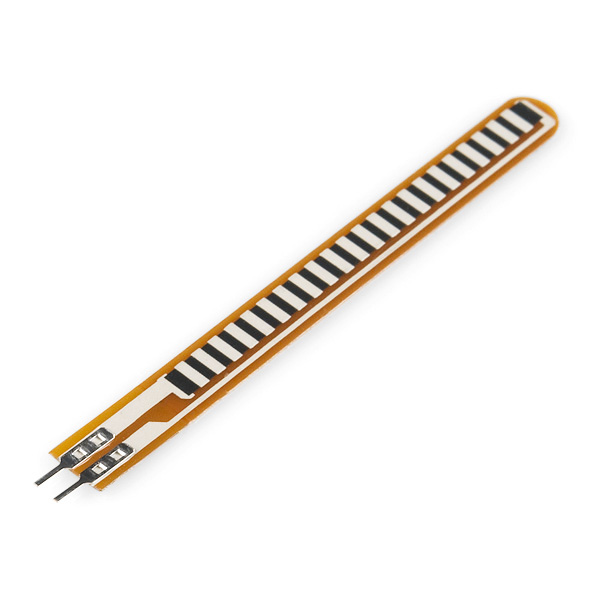
I have decided to use the flex sensors in a voltage divider. If you look at the schematic, you will notice that R1 (resistor to Vcc) is 47k, while R2 (resistor to ground) is the flex sensor.
    • The more the flex sensor flexes, the more resistance there is on R2, and more power can flow through R1. The more the flex sensor flexes, more voltage is let pass.
Let's look at an example:
  1. The ball hits the backboard
  2. The backboard vibrates more than the rim
  3. More voltage is passed from the backboard than the rim
  4. The microcontroller compares the voltages.
    • If backboard >= rim, do nothing
  1. The ball hits the rim
  2. The rim vibrates more than the backboard
  3. More voltage is passed from the rim than the backboard
  4. The microcontroller compares the voltages.
    • If rim > backboard, buzz and restart the shot clock

Manual controls

The manual controls are connected to the same I/O pins as the sensors. In the end, the I/O pin is only sensing whether that pin is HIGH or LOW.


That's all I have for now.
What needs to be done:
  • Flex sensor
  • test on an actual (indoor) basketball hoop
  • make a PCB to get rid of all the clumsy wires

Here is the code

I used an attiny44 @ 8mhz internal, USBtinyISP as the programmer.

//Made  by TS Wang
//6/1/2013
//Documentation on this project can be found on http://tswangshotclock.blogspot.com/
/*
This project is meant to further improve Spalding's (r) shot clock.

The problems with that shot clock:
-picks up backboard vibration
-does not pick up net shots

Improvements by this shot clock:
-ignores backboard vibration
-picks up on net shots
-allows manual control from the bench
  -manual stop-where-its-at
  -manual stop-and-restart
  -manual stop (reset)
  -manual stop-and-jump-to-zero (if that is useful at all)

This project can be replicated. Replicate all you want.*/

//Attiny44 @ internal rc 8mhz

int latchone = 10;  //ST_CP or 12      Last
int clockone = 9; //SH_CP or 11      Second
int dataone = 2; //DS or 14           FIRST

int latchtwo = 3;
int clocktwo = 4;
int datatwo = 5;

int beeper = 6;

int sensor = 7;
int good = 500;

int readstop = 8;

int sec;

byte digitone[11]= {0x00 ,0x30, 0x6D, 0x79, 0x33, 0x5B, 0x5F, 0x70, 0x7F, 0x7B, 0x7E};

void setup() {
  pinMode(latchone, OUTPUT); pinMode(clockone, OUTPUT); pinMode(dataone, OUTPUT);
  pinMode(latchtwo, OUTPUT); pinMode(clocktwo, OUTPUT); pinMode(datatwo, OUTPUT);
  pinMode(beeper, OUTPUT);
  pinMode(sensor, INPUT); pinMode(readstop, INPUT);
}

void loop() {reading();}


/*************analog reading***********/
void reading() {
  if(digitalRead(readstop) == HIGH) {
    spaztwo();
  }
  if(analogRead(sensor) >= good) {
    spaz();
  }
  else{} 
}
/***************countdown and analog reading****************/
void thedeal() {
  while (sec >= 0){
    countdown(sec);
    sec = sec - 1;
    
    for (int i = 0; i<600; i++){ //change this ~ seconds
      reading();
      compare();
      delay(1);
    }
  }
  sec = 24;
}
/****************blink and restart*************/
void spaz() {
  sec = 24;
  countdown(sec);
  digitalWrite(beeper, HIGH);
  delay(250);
  digitalWrite(beeper, LOW);
  delay(250);
  digitalWrite(beeper, HIGH);
  delay(250);
  digitalWrite(beeper, LOW);
  delay(250);
  sec = 23;
  thedeal();
}

/****************blink and stop***************/
void spaztwo() {
  if (analogRead(sensor) >= good) { 
    digitalWrite(beeper, HIGH);
    delay(250);
    digitalWrite(beeper, LOW);
    delay(250);
    digitalWrite(beeper, HIGH);
    delay(250);
    digitalWrite(beeper, LOW);
    delay(250);
    thedeal();
  }
  else{spaztwo();}
}


/**************comparing backboard to rim vibration**************/

void compare () {
  int backboard = analogRead(0);
  int rim = analogRead(1);
  if (rim > backboard) {
    spaz();
  }
  else {}

}


/*countdown code*/
void countdown(int NTD) {
  switch (NTD) {
    case 24:
      digitalWrite(latchone, LOW);
      digitalWrite(latchtwo, LOW);
      shiftOut (dataone, clockone, LSBFIRST, digitone[2]);
      shiftOut (datatwo, clocktwo, LSBFIRST, digitone[4]);
      digitalWrite(latchone, HIGH);
      digitalWrite(latchtwo, HIGH);
      break;
      
    case 23:
      digitalWrite(latchone, LOW);
      digitalWrite(latchtwo, LOW);
      shiftOut (dataone, clockone, LSBFIRST, digitone[2]);
      shiftOut (datatwo, clocktwo, LSBFIRST, digitone[3]);
      digitalWrite(latchone, HIGH);
      digitalWrite(latchtwo, HIGH);
      break;

    case 22:
      digitalWrite(latchone, LOW);
      digitalWrite(latchtwo, LOW);
      shiftOut (dataone, clockone, LSBFIRST, digitone[2]);
      shiftOut (datatwo, clocktwo, LSBFIRST, digitone[2]);
      digitalWrite(latchone, HIGH);
      digitalWrite(latchtwo, HIGH);
      break;

    case 21:
      digitalWrite(latchone, LOW);
      digitalWrite(latchtwo, LOW);
      shiftOut (dataone, clockone, LSBFIRST, digitone[2]);
      shiftOut (datatwo, clocktwo, LSBFIRST, digitone[1]);
      digitalWrite(latchone, HIGH);
      digitalWrite(latchtwo, HIGH);
      break;
      
    case 20:
      digitalWrite(latchone, LOW);
      digitalWrite(latchtwo, LOW);
      shiftOut (dataone, clockone, LSBFIRST, digitone[2]);
      shiftOut (datatwo, clocktwo, LSBFIRST, digitone[10]);
      digitalWrite(latchone, HIGH);
      digitalWrite(latchtwo, HIGH);
      break;
      
    case 19:
      digitalWrite(latchone, LOW);
      digitalWrite(latchtwo, LOW);
      shiftOut (dataone, clockone, LSBFIRST, digitone[1]);
      shiftOut (datatwo, clocktwo, LSBFIRST, digitone[9]);
      digitalWrite(latchone, HIGH);
      digitalWrite(latchtwo, HIGH);
      break;
      
    case 18:
      digitalWrite(latchone, LOW);
      digitalWrite(latchtwo, LOW);
      shiftOut (dataone, clockone, LSBFIRST, digitone[1]);
      shiftOut (datatwo, clocktwo, LSBFIRST, digitone[8]);
      digitalWrite(latchone, HIGH);
      digitalWrite(latchtwo, HIGH);
      break;
      
    case 17:
      digitalWrite(latchone, LOW);
      digitalWrite(latchtwo, LOW);
      shiftOut (dataone, clockone, LSBFIRST, digitone[1]);
      shiftOut (datatwo, clocktwo, LSBFIRST, digitone[7]);
      digitalWrite(latchone, HIGH);
      digitalWrite(latchtwo, HIGH);
      break;
    case 16:
      digitalWrite(latchone, LOW);
      digitalWrite(latchtwo, LOW);
      shiftOut (dataone, clockone, LSBFIRST, digitone[1]);
      shiftOut (datatwo, clocktwo, LSBFIRST, digitone[6]);
      digitalWrite(latchone, HIGH);
      digitalWrite(latchtwo, HIGH);
      break;
    case 15:
      digitalWrite(latchone, LOW);
      digitalWrite(latchtwo, LOW);
      shiftOut (dataone, clockone, LSBFIRST, digitone[1]);
      shiftOut (datatwo, clocktwo, LSBFIRST, digitone[5]);
      digitalWrite(latchone, HIGH);
      digitalWrite(latchtwo, HIGH);
      break;
    case 14:
      digitalWrite(latchone, LOW);
      digitalWrite(latchtwo, LOW);
      shiftOut (dataone, clockone, LSBFIRST, digitone[1]);
      shiftOut (datatwo, clocktwo, LSBFIRST, digitone[4]);
      digitalWrite(latchone, HIGH);
      digitalWrite(latchtwo, HIGH);
      break;
    case 13:
      digitalWrite(latchone, LOW);
      digitalWrite(latchtwo, LOW);
      shiftOut (dataone, clockone, LSBFIRST, digitone[1]);
      shiftOut (datatwo, clocktwo, LSBFIRST, digitone[3]);
      digitalWrite(latchone, HIGH);
      digitalWrite(latchtwo, HIGH);
      break;
    case 12:
      digitalWrite(latchone, LOW);
      digitalWrite(latchtwo, LOW);
      shiftOut (dataone, clockone, LSBFIRST, digitone[1]);
      shiftOut (datatwo, clocktwo, LSBFIRST, digitone[2]);
      digitalWrite(latchone, HIGH);
      digitalWrite(latchtwo, HIGH);
      break;
    case 11:
      digitalWrite(latchone, LOW);
      digitalWrite(latchtwo, LOW);
      shiftOut (dataone, clockone, LSBFIRST, digitone[1]);
      shiftOut (datatwo, clocktwo, LSBFIRST, digitone[1]);
      digitalWrite(latchone, HIGH);
      digitalWrite(latchtwo, HIGH);
      break;
    case 10:
      digitalWrite(latchone, LOW);
      digitalWrite(latchtwo, LOW);
      shiftOut (dataone, clockone, LSBFIRST, digitone[1]);
      shiftOut (datatwo, clocktwo, LSBFIRST, digitone[10]);
      digitalWrite(latchone, HIGH);
      digitalWrite(latchtwo, HIGH);
      break;
    case 9:
      digitalWrite(latchone, LOW);
      digitalWrite(latchtwo, LOW);
      shiftOut (dataone, clockone, LSBFIRST, digitone[10]);
      shiftOut (datatwo, clocktwo, LSBFIRST, digitone[9]);
      digitalWrite(latchone, HIGH);
      digitalWrite(latchtwo, HIGH);
      break;
    case 8:
      digitalWrite(latchone, LOW);
      digitalWrite(latchtwo, LOW);
      shiftOut (dataone, clockone, LSBFIRST, digitone[10]);
      shiftOut (datatwo, clocktwo, LSBFIRST, digitone[8]);
      digitalWrite(latchone, HIGH);
      digitalWrite(latchtwo, HIGH);
      break;
    case 7:
      digitalWrite(latchone, LOW);
      digitalWrite(latchtwo, LOW);
      shiftOut (dataone, clockone, LSBFIRST, digitone[10]);
      shiftOut (datatwo, clocktwo, LSBFIRST, digitone[7]);
      digitalWrite(latchone, HIGH);
      digitalWrite(latchtwo, HIGH);
      break;
    case 6:
      digitalWrite(latchone, LOW);
      digitalWrite(latchtwo, LOW);
      shiftOut (dataone, clockone, LSBFIRST, digitone[10]);
      shiftOut (datatwo, clocktwo, LSBFIRST, digitone[6]);
      digitalWrite(latchone, HIGH);
      digitalWrite(latchtwo, HIGH);
      break;
    case 5:
      digitalWrite(latchone, LOW);
      digitalWrite(latchtwo, LOW);
      shiftOut (dataone, clockone, LSBFIRST, digitone[10]);
      shiftOut (datatwo, clocktwo, LSBFIRST, digitone[5]);
      digitalWrite(latchone, HIGH);
      digitalWrite(latchtwo, HIGH);
      break;
    case 4:
      digitalWrite(latchone, LOW);
      digitalWrite(latchtwo, LOW);
      shiftOut (dataone, clockone, LSBFIRST, digitone[10]);
      shiftOut (datatwo, clocktwo, LSBFIRST, digitone[4]);
      digitalWrite(latchone, HIGH);
      digitalWrite(latchtwo, HIGH);
      break;
    case 3:
      digitalWrite(latchone, LOW);
      digitalWrite(latchtwo, LOW);
      shiftOut (dataone, clockone, LSBFIRST, digitone[10]);
      shiftOut (datatwo, clocktwo, LSBFIRST, digitone[3]);
      digitalWrite(latchone, HIGH);
      digitalWrite(latchtwo, HIGH);
      break;
    case 2:
      digitalWrite(latchone, LOW);
      digitalWrite(latchtwo, LOW);
      shiftOut (dataone, clockone, LSBFIRST, digitone[10]);
      shiftOut (datatwo, clocktwo, LSBFIRST, digitone[2]);
      digitalWrite(latchone, HIGH);
      digitalWrite(latchtwo, HIGH);
      break;
    case 1:
      digitalWrite(latchone, LOW);
      digitalWrite(latchtwo, LOW);
      shiftOut (dataone, clockone, LSBFIRST, digitone[10]);
      shiftOut (datatwo, clocktwo, LSBFIRST, digitone[1]);
      digitalWrite(latchone, HIGH);
      digitalWrite(latchtwo, HIGH);
      break;
    case 0:
      digitalWrite(latchone, LOW);
      digitalWrite(latchtwo, LOW);
      shiftOut (dataone, clockone, LSBFIRST, digitone[10]);
      shiftOut (datatwo, clocktwo, LSBFIRST, digitone[10]);
      digitalWrite(latchone, HIGH);
      digitalWrite(latchtwo, HIGH);
      break;
  }
}

All documents can be found on my Google Drive:
https://drive.google.com/folderview?id=0B5gFDZ2efTDSX0hPdG5sWWJuemc&usp=sharing
Files will be added.

Please ask questions in the comments.

This is the shot clock that will change the game.

Shot Clock (1)

This Blog will be a chain of updates to TS Wang's Shot Clock design.

Have you all seen this automatic resetting shot clock yet? Not many people like it, and it's not worth the price.
Problems with it:
  • Picks up backboard vibrations
  • Does not sense net-shots
  • Manual controls are difficult to access.
Well, I am designing a new automatic shot clock that will fix these issues.
This new shot clock will:
  • sense net-shots (with a laser-phototransistor setup)
  • ignore backboard vibrations (by comparing voltages generated by rim vibrations versus backboard vibrations)
  • have manual controls to...
    • Reset the shot clock to 24 and count down again
    • Pause the shot clock at it's current number and wait for a signal to continue
    • Reset the shot clock (sleep mode)
    • Jump to "0" on the shot clock and stop (this was a glitch, but it might be helpful)
  • count down from 24 and stop at "0" (shot clock violation)*
What are the benefits of having an automatic resetting shot clock?
  • no more human mistakes that might lead to inaccurate and imprecise timing
  • fairness in the game of basketball
  • Does anyone remember this incident?
Basketball fans, wait no longer.
This is the shot clock that will change the game.
Well Hello!

This is my first time ever blogging.
This is a test blog.

Goodbye!